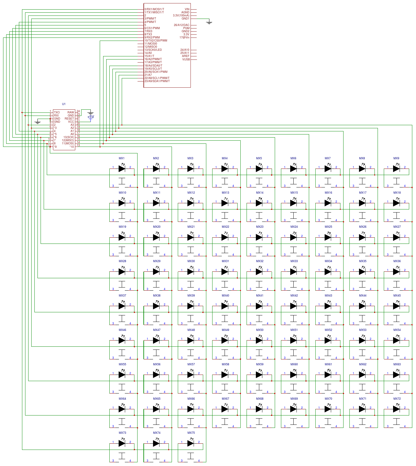
5x15 grid layout, multiple controllers supported
The matrix is a 9x9 grid. This uses all of the available pins on the Pro Micro. The other controllers have pins left over. The serial pins and pins connected to LEDs were avoided if possible.
Construction
Two PCBs are used as the top and bottom plates. M2 spacers are used to connect the two plates. The length of the spacers depends on the controller used. The mini USB connector on the Teensy 2.0 is taller than the others. 6mm spacers were used for the ones with micro USB connectors. Switches are PCB mount. 1n4148 diodes are installed inside the switches. POS type keycaps designed to cover more than one switch are used for some switch locations.
Firmware
TMK used for
Pro Micro and Teensy 2.0. The only difference is the pinout.
TMK/Chibios used for the
Teensy LC/3.2. Instructions for adding Chibios to TMK are
here.
Kiibohd controller can be used for the Teensy 3.2 Instructions for creating a custom keyboard with a Teensy 3.2 are
here.
The specific files that were created follwing the instructions above are here:
Pictures
 |
| Bottom of 1.0 PCB with Pro Micro installed |
 |
| Top and bottom PCBs assembled, Pro Micro sandwiched between. |
 |
| Diodes installed inside the switches. |
 |
| Grab bag DSA caps. 2u POS caps covering two switch positions. |
 |
| Pro Micro |
 |
| PJRC Teensy 2.0 |
 |
| PJRC Teensy 3.2 |
 |
| PJRC Teensy LC |
 |
| Empty socket. Teensy 2.0/LC/3.2 |
 |
| Gateron yellows and Gateron clears for 2u POS switches |
|
 |
| Bottom of 1.1 PCB. White border added to make it look more like a highway sign. |