Wednesday, September 30, 2020

Yin and Yang

Two very different Gherkins

Two different Gherkin PCBs, one built for the Seeedstudio Xiao and the other for the ATmega32A using V-USB.

Both have the same shape and mounting hole positions as the regular Gherkin PCB. The Gherkin32 has a Mini USB connector sticking out where the Pro Micro would have been.

The GherkinX has a 5x6 diode matrix like the original Gherkin. It uses all 11 available pins on the Xiao.

The Gherkin32 has no matrix diodes. Each individual switch is connected to it's own pin on the  ATmega32A. 30 pins for the switches and the remaining 2 for the V-USB connection.

Possible to fit everything with 6mm spacers. Low profile Peel-A-Way sockets.


Monday, September 28, 2020

ATmega324PA

Cheap ATmega32A alternative at Digikey

The ATmega324PA-PN is the industrial temperature rated version which usually cost more. It is a non-stock item at Digikey and they seem to be trying to get rid of them. At $2.04 each they are much cheaper than the ATmega32A. It is a newer (though still fairly old) generation chip than the ATmega32A. It shares the same pinout. It can also run at up to 20MHz while the ATmega32A runs at 16MHz. 

It is not a drop in replacement. A compiled hex file for the ATmega32 will not run on the ATmega324PA. It will need to be recompiled with the ATmega324PA as the target.

The only modifications I had to make to the 108 code was to change the MCU from atmega32a to atmega324pa and comment out the line that defines the timer register on the ATmega32.

I also compiled a version of the USBaspLoader for the ATmega324PA, same as for the ATmega32, just changing the MCU. The fuses are the same as for the ATmega164.


Wednesday, September 23, 2020

nobbs

16 rotary encoders on a Teensy LC

Using the Arduino CommonBusEncoders library it is possible to connect multiple encoders in a keyboard like matrix.

There is a single common data pin for the Encoder A and Encoder B signals. If there is a switch built in then one pin of the switch is also connect to a single bus data pin. The ground pin of each encoder is connected to it's own data pin. The tutorial PDF explains the topology.

16 encoders and 10 APA106 LEDs connected to a Teensy LC. 

There is a second pin 17 on the Teensy LC that has a level converter for the 5v output that the APA106 requires. The rest of the pins run at 3.3v logic. I have a tiny solder bridge jumper that connects either the regular 3.3v pin 17 or the level converted pin 17 to the APA106. When connected to the 3.3v output pin the LEDs flickered randomly. On the Seeeduino Xiao the 3.3v output works fine driving the APA106 without level conversion.

16 encoders with 3 diodes each to prevent ghosting.

I made a simple plate to hold everything in place. Much sturdier than without.

The encoders are spaced the same as MX switches. Small tapered knobs work best.

Side view. M2 spacers and screws holding a second PCB as the base.

A second built with different encoders. These have the split spline shaft instead of the D shaped shaft. The purple Teensy LC is from OSH Park.


Monday, September 21, 2020

Gherkin Express 2 with blue LEDs

Swapped the zener diodes for blue LEDs

0805 LEDs fit the SOD123 footprint. Installed blue LEDs in reverse polarity and it works.

D+ is always on, D- only when there is data being transmitted.

The 4 Gherkin Express 2 that have been completed so far. I have one PCB left.

Friday, September 18, 2020

108 key

Second SMT order from JLCPCB

$8 discount on 100mm x 100mm PCB assembly. This time with 110 4.5mm tactile switches. The only parts not assembled by JLCPCB were the Mini USB connector, ICSP header, PTC fuse and the socket for the ATmega32a.

I ordered 5 PCB's and had 2 assembled. I received the 3 unassembled boards with the 2 completed ones. I used the blank PCB as the bottom.

I used blue LEDs for the V-USB voltage regulator. These were basic items so did not have a setup fee. There is only one extended part, the tactile switches. $3 total additional setup fee. I also placed a footprint for standard zener diode in case the blue LEDs did not work.

The switches are rotated 15 degrees and overlapped to position them as close as possible and still have a square grid. On this particular board they had to manually solder the bottom right switch. I could tell because of the flux residue and there is much more solder on those joints than any of the others. The second board I received was perfect.

Every data pin on the ATmega32a is in use. 12 columns and 9 rows. 5 status LEDs. The USBASP switch on PD7 and the ICSP pins on the header. PD2 and PD4 for the V-USB connection. Same as I use on the ATmega328 on the Aardvark.

TMK supports the ATmega32 with this fork https://github.com/nuess0r/tmk_keyboard


Thursday, September 17, 2020

Gherkin Express TH

Credit Card sized through hole component Gherkin

This shares the same V-USB parts and configuration as the Aardvark and the same matrix and firmware as the Gherkin Express 2.

The main PCB is the standard 1.6mm thickness. The top and bottom plates are 0.8mm thick. JLCPCB will do 0.8mm in other colors for cheap, 0.6mm is only cheap in green soldermask.

The ICSP header is the tallest part. I built one with it to test, but have omitted it from the others so I could fit the top.

The holes in the top are 4mm for the switches and 3mm for the LEDs. The RESET and USBASP switches are shorter than the others.

With a full size socket and the 6.5mm tall resonator 8mm spacers were needed to fit the top piece. 9.5mm tall switches were used.

The lowest profile possible with 4mm spacers. 7mm tall switches are used. No socket for the ATmega328 and the resonator and power capacitor are replaced with the SMT parts from the Gherkin Express.

I use a 1.6mm thick brass nut as a spacer for the bottom piece. The bottom of the switch pins were trimmed. On the full height it has two 1mm thick nylon washers.

I will try replacing the resonator with a miniature through hole crystal and a smaller power capacitor.

Same outer dimensions as the Gherkin Express and Gherkin Express 2.


Wednesday, September 16, 2020

Shine of the Rainbow

Volume Control

I made a rotary encoder with 12 RGB LEDs. I programmed it as a volume control. Pressing down on the knob toggles mute.

The LEDs are the same APA106 5mm WS2812B compatible LEDs I used in the Aardvark. The controller is the Seeedstudio Xiao.

The top plate has 5mm holes in the exact position of the LEDs on the main PCB. When soldering the LEDs I used the top plate to keep the LEDs positioned so they line up perfectly.

The top plate is held in place by the rotary encoder's screw on nut. The bottom is another PCB held on with M2 spacers and screws.

The bottom of the PCB has the same silkscreen pattern as the top.

The board is running an Arduino Sketch. It uses the Adafruit Neopixel library to control the LEDs. The HID Project library for sending keyboard commands to the host computer. The CommonBusEncoders library is used to talk to the encoder.

Friday, September 11, 2020

SMT assembly

Gherkin Express2 with SMT assembly at JLCPCB

I wanted to try out the SMT assembly service at JLCPCB. They were having a special with a $8 discount coupon.

The first thing to realize with this service is that there are a lot of restrictions:

  • Green solder mask only
  • 1mm, 1.2mm, 1.6mm thick PCB only
  • Assemble one side only. You choose top side or bottom when ordering. Put all your SMT parts on one side if possible.
  • 1oz copper (the usual)
  • 100x100mm max size for the promotional discount, otherwise 480x320mm max size.
  • You need tooling holes added to your PCB. You can add them yourself or let them do it.
  • 2, 5 or 10 pieces assembled, no other options. You either get 2 assembled or all 5, or 10 of your PCB order. If you only get 2 assembled the remainder of the blank PCBs are returned with your order 
  • You do not get the solder stencil with your order
  • Only parts in stock in the JLCPCB inventory are available for assembly. Any other parts even if LCSC has them will be skipped.
  • Extended non-BASIC parts have a $3 setup fee.

Since I could not do a 0.6mm thick PCB like the Gherkin Express I redesigned it to have a regular micro USB connector. JLCPCB does not have any USB connectors in inventory so this is an item that will have to be soldered on manually.

The 5.1mm tactile switches were in their inventory but as an Extended item, so there is a one time $3 charge to use them.

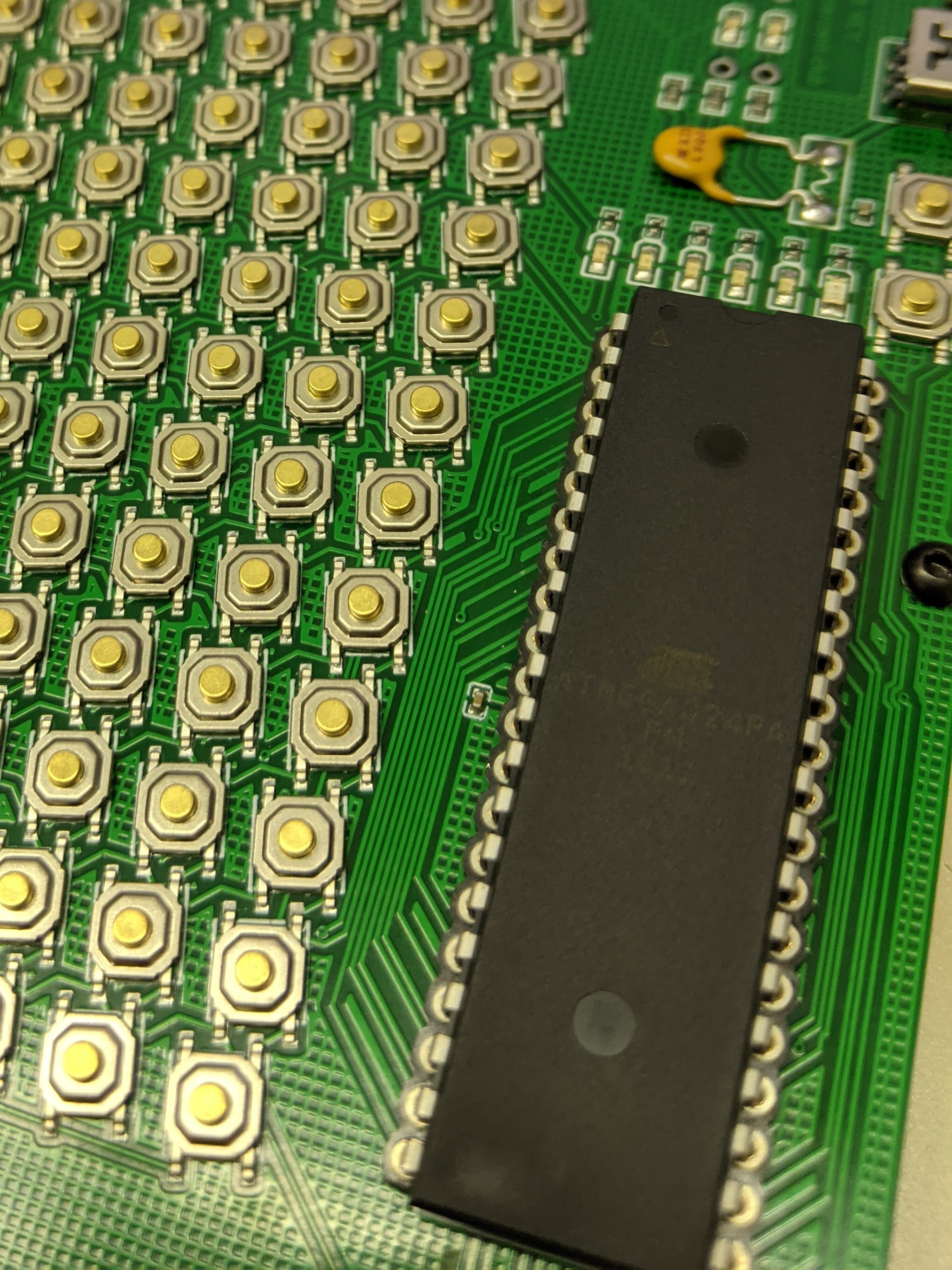
They were also out of stock on the ATmega32U2, but they do have the ATmega328p and it is a BASIC part, so no setup fee. I redesign the Gherkin Express 2 as a V-USB board.

The rest of the items needed I found the BASIC equivalent to save on setup fees. The only items I could not find a BASIC part for were the fuse and the 3.6v zener. I have zener diodes so I left those out but included the Extended fuse part.

$6 total for setup of the tactile switches and the fuse Extended parts.

Designing the PCB using EasyEDA and selecting all the parts through their library makes it easy to export the BOM and pick-and-place file that JLCPCB needs for assembly. It is also in the format they accept so no editing is needed. Just export from the fabrication menu in EasyEDA, save to a file and import to JLCPCB.

There is a demo on JLCPCB that goes through the ordering process.

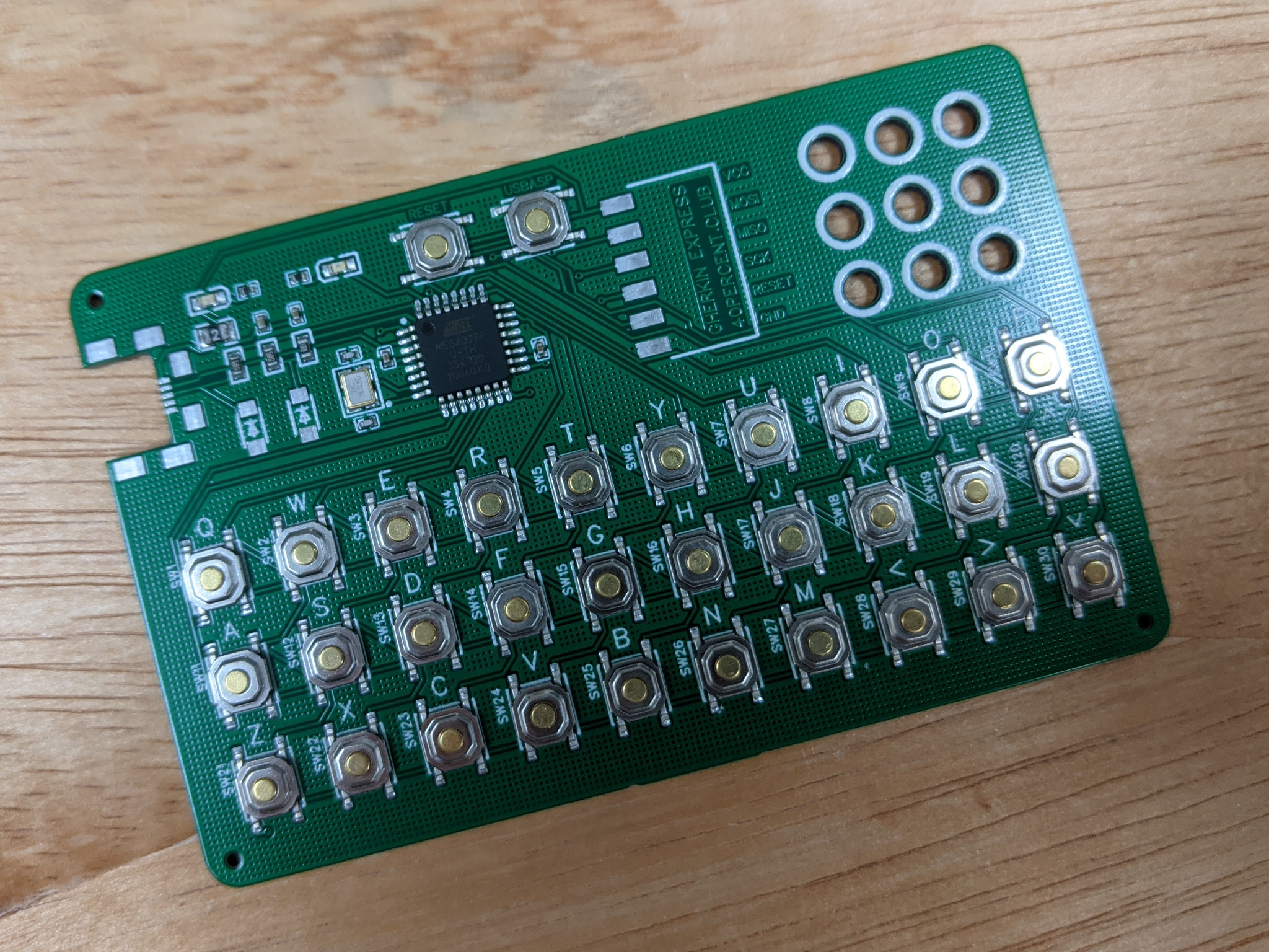
The preview in JLCPCB shows the placement and orientation of all the parts. The USB connector and the 2 zener diodes are not populated and will not be assembled.You can see the 3 tooling holes in the corners.

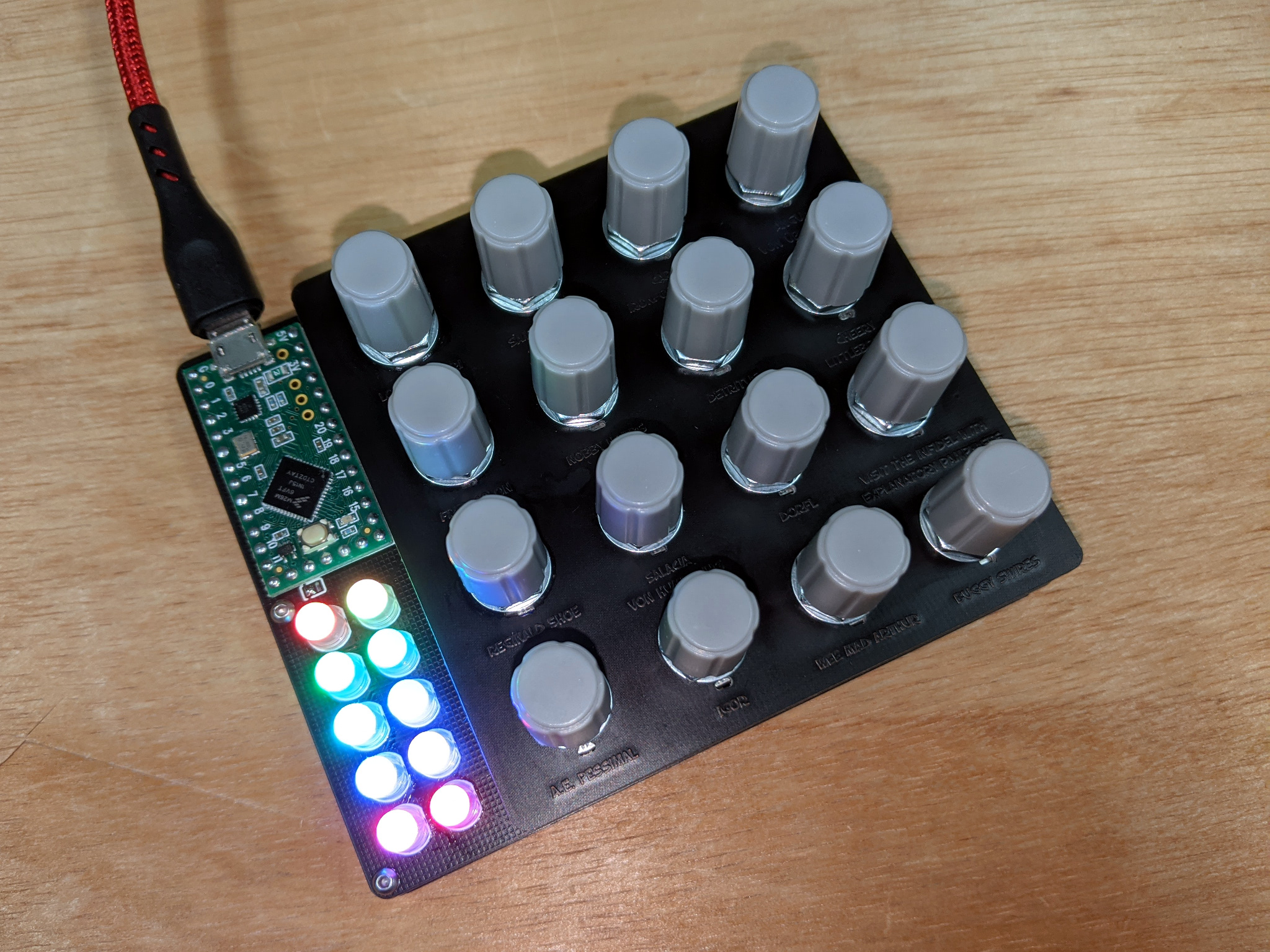
This is what was received. Everything as expected. Only the USB connector and zener diodes to be added.

Remaining parts soldered on.

I tried 3 different USB connectors. The one on the left is the incorrect part for this footprint. It does line up enough to work. The middle one is the correct part, it has reinforcing flanges on the front of the connector. The one on the right is the version of the connector without flanges, makes it a little lower profile.

Edge view of the 3 different connectors. Also 2 of the original Gherkin Express above. The highest part of the board are the switches.

5 keyboards in an Altoids tin.

A few more could fit.

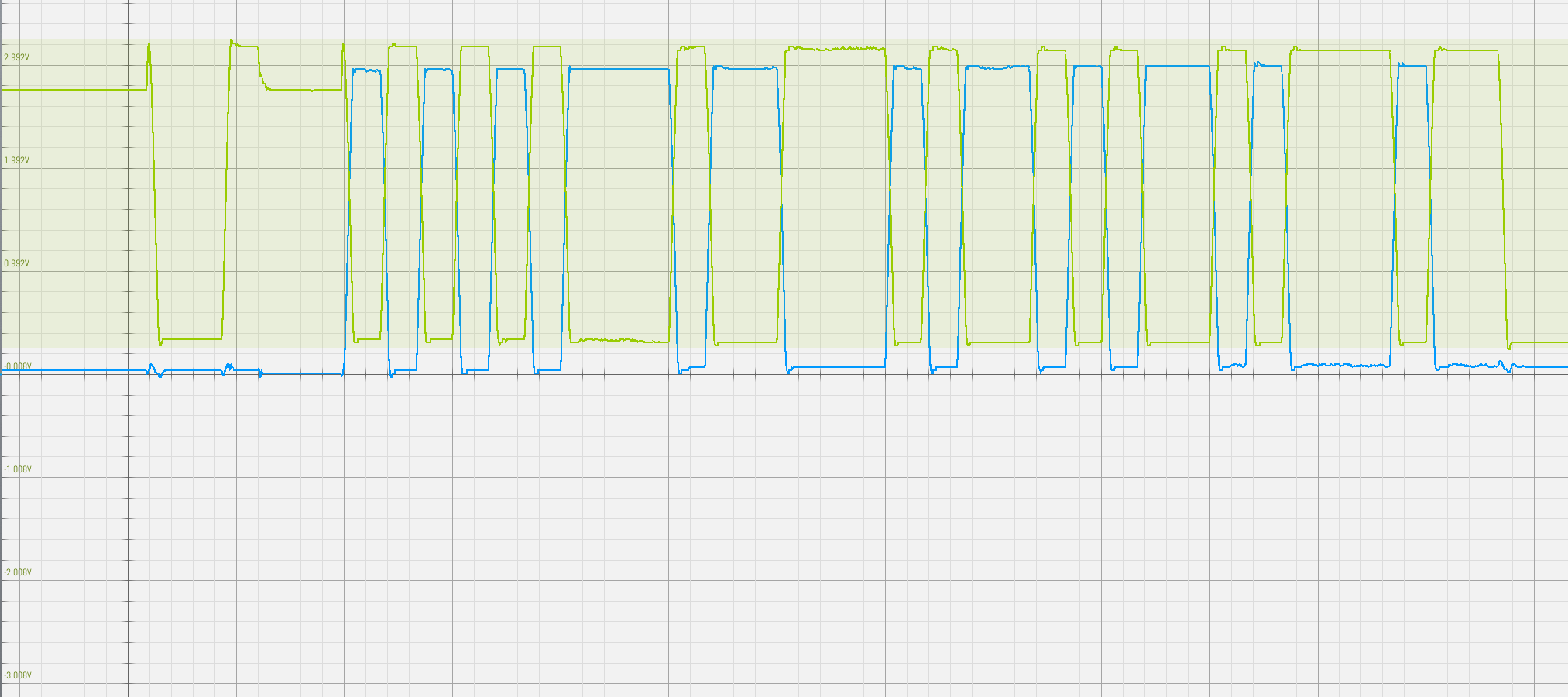
Since these have an ATmega328p there is no bootloader. I made a pogo pin jig to connect to the ISP pads. Once flashed with the USBasploader it can be flashed via USB as a USBasp device. The reset and usbasp switches work the same as on the aardvark. It uses the same bootloader as the aardvark.


The total cost for 5 assembled boards with all the parts included was $32.32, this is with the $8 coupon applied. Add to that the cost of the PCB $5 and shipping. If you order other PCBs at the same time they will wait the 1-2 days for SMT assembly and all ship together.

Thursday, September 10, 2020

Blue LEDs instead of zener diodes in V-USB

Tested some blue LEDs in the aardvark

For low speed USB the data lines use 3.3 volt logic levels. 0-0.3v is a logic low and 2.8-3.6v is a logic high.

3.6v zener diodes are commonly used in V-USB hardware to clip the 5v output to ~3.3v. Blue LEDs can also have a similar effect.

I got this idea from the Sparkfun AVR Stick. I previously used it in my phantom keystroker.

The blue LEDs are installed in opposite polarity to how the zener diode would have been. I chose the lowest brightness (MCD), diffused LED I could find on Digikey. These are 3mm "ice cube" square LEDs. Not a common size. They are still quite bright.

This may not work with any random blue LEDs. They are being used in a way not intended.

Since the USB signal is differential D+ is high when idle and D- is low. So most of the time the LED on D+ will be lit and D- will be off. When data is being transmitted D+ will flicker low and D- will flicker on.

zener diodes

I hooked D+ and D- to a scope and the voltage levels are within USB spec. This graph is V-USB with 3.6 zener diodes. Green is D+ and Blue is D-. The minor graduations in the graph are 0.2v.

blue LEDs

This graph is the blue LEDs. Voltage are lower than with the zener diodes, but still within range.

Teensy 3.2

For comparison this is a Teensy 3.2 which has a hardware USB transceiver. The Teensy also transmits at a much higher rate than the slow software driven V-USB.